Meet Fluidit 2.5 Suite
Faster and More Versatile!
We are excited to introduce Fluidit Suite’s latest and most powerful update, designed to enhance your modeling experience with increased speed, improved performance, and greater versatility. Explore the highlights of this release and experience the full potential of Fluidit 2.5.
2.5 Release Highlights

Improved simulation and UI performance for city-wide models.

Optimize & Calibrate Tool: an easy-to-use, generic tool for calibrating and optimizing any aspects of the hydraulic models.

More versatile profile figures for network analysis and scenario comparison.

Fluidit Storm: refined capabilities for 2D simulations and completely new alternative hydrological models added for Mike+ compatibility.

Fluidit Heat: much improved 5th generation energy system modeling capabilities.
Detailed overview of
General Updates
- The new Optimize & Calibrate tool can optimize and calibrate any numerical aspects of the model.
Input a component design variable(s) to be adjusted and a cost function. The Optimize & Calibrate tool modifies your design variable based on your preference (list of accepted values, range, or groups), trying to minimize the cost function, which can be, for example, pumping costs, amount of leaks, or difference in measured and modeled pressure. In Fluidit, we successfully used the tool to calibrate valve openness state, localize leaks, and define a safe hydrant discharge limit, but the tool has much wider potential! - Major speed boost for models using a high number of long time series.
For example, in a model with 5000 time series, the loading time was reduced from 1 min 25 seconds (2.4 version) to just 12 seconds (2.5 version). This change is not compatible with versions older than 2.4.3 (February 2024). - Loading scenarios and models is faster, especially with larger models.
Calculation of the derivative results (min, max, avg) is significantly faster than before. For large models, the scenario loading times are halved! For example, in a model with 200,000 components, the scenario loading time was reduced from 55 seconds to 30 seconds.
- Patterns can now use custom time step length.
This allows, for example, more detailed modeling of demands/inflows. - Demand multipliers can be added to the Zones.
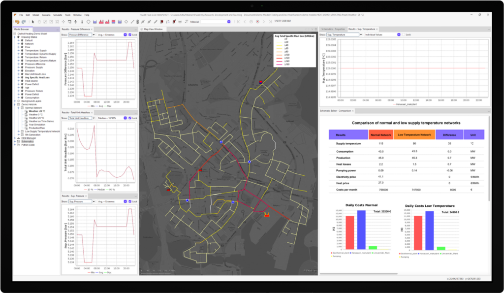
These are also scenario-specific and inheritable! - The updated Profile Figure allows for a separate selection of lines to draw for each scenario.
For example, min head, max head, current, critical, etc. The user has more freedom to customize each line type used. - Components and their results can now be exported in Excel format.
- New DEM Modification Line components can be used to edit, cut, and slope the DEM in a certain direction.
For example, create streams or channels onto the digital terrain model for 2D flood modeling. - Result Window now supports results from multiple scenarios.
Right-click the Result window and select Show Other Scenario. The results from the other scenario are shown with a dashed line. - Report steps can be set individually for scenarios for more flexible and detailed modeling.
Product-Specific Highlights
Fluidit 2.5 brings a wealth of new features and improvements across all our product lines. Explore the detailed highlights for Fluidit Heat, Fluidit Storm, and Fluidit Water below.

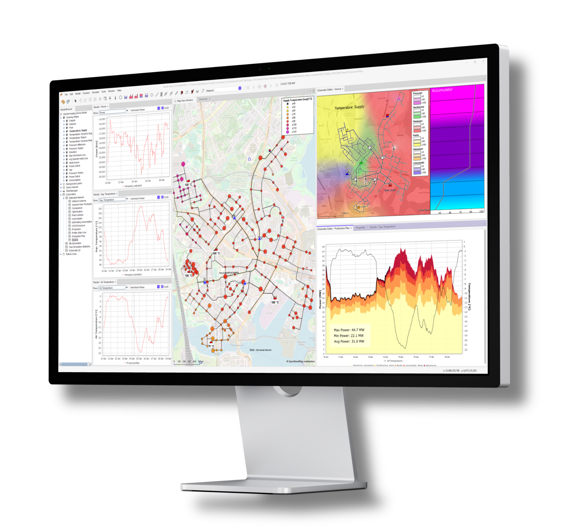
- The new demand response control feature scenario specific simulation of various demand side management operations such as peak shifting load shedding, etc. The tool tracks the demand surplus or deficit and will restore the balance during the recharge time period, after the changes in the pattern end and an optional delay period is done. This allows quite easy and powerful way to model demand response to even out the morning & evening spikes by reducing the space heating energy consumption.
- New schematic figure for accumulators shows water temperature in different measurement levels in the accumulator specified by the measurement levels. With the figure user can now analyze temperature levels and gradients in the accumulator through the simulation. By clicking the next time step button or play time steps button, the figure shows how the temperature elements and levels change in the accumulator as the simulation progresses.
- Heat exchanger component is now reimplemented for Heat simulations. This fixes multiple problematic cases with linked heat exchangers, control device behavior, same side heat exchangers and adds features, such as approach temperature.
- The control valve in junctions can be replaced with a pump. This allows, for example the simulation of decentralized pumping in district heating and cooling networks as well as fifth generation networks.
- Heat exchangers and pump batteries/valves can be used as production units in production plans. Pumps and valves are “virtual” sources – their settings are not changed (they are assumed to be dp controlled). Instead, the power taken from them is reduced from the power taken from the other sources.
- New weather measurement Points for regional temperature & wind values. If the model has any Weather Measurement Points defined, the closest one is used for the climate parameters when calculating demands, cooling etc. This allows for the simulation of varying weather conditions in the same scenario.
- Production plans have new features and results: Plans with dp control will have dp control activated with the last active plant in the hierarchy and other with max power setting. Pump batteries, heat exchangers and valves can be used as units in production plans. Pumps and valves are “virtual” sources – their settings are not changed (they are assumed to be dp controlled. The new results include plan power demand which indicates the power demand for the zone and active plan actions which indicate the last active unit index in the plan.
- Accumulator has new results and properties: The new results include hot/cold volume and stored energy: The supply / return pipe connection to the accumulator can now be spesified by the user and spesified pumps with definitions can be now added for accumulators.

- 1D simulator updated (merged with OWA SWMM 5.2.4)
- Increased compatibility with MikeUrban/Mike+ models.
- New Time-Area runoff catchments.
- User-defined coupling area for improved 1D-2D simulations.
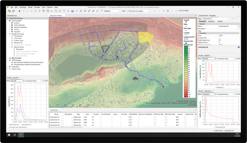
- Support added to activate multiple cells to interact with coupled nodes, Flood Culvert and Inflow components. User can define the surface area of 2D active cells that will be coupled with 1D junctions or 2D culvert components. Now both 1D and 2D models are synchronized to use the exact same size for improved stability and connectivity to multiple cells. Additionally, the culvert inlet and outlet can be better aligned with the connecting channels for improved performance.
- Added support for specifying a blockage coefficient for coupled nodes in 1D/2D simulations. This new parameter is applied to the flow calculated by Rating Curve or Orifice Coefficient enabling the user to account for partial or full blockage of 1D/2D inlets.
- “2D Only” and “Manual” flood simulation types are now more convenient and faster. The simulate button (or F5) will now simulate all “2D only” or “Manual” Flood Model Area(s) if Flood Model Area(s) is selected or there are no 1D components in the model.
- Orifice coefficient unit in the coupled 1D-2D flood simulations now follows the model unit. This was previously based on the assumption that m³/s was the model unit. In practice, this means that for the default l/s units, the coefficients need to be multiplied by a thousand to obtain the same results in 2.5 as in 2.4.
- “2D Flood Culvert” component has become a more powerful tool in Storm with leveraged developments. With a partially full flow calculation, culvert flows are stable and accurate. Time series results for 2D Culvert components are now available. These developments, combined with more active cells (also a new feature), ensure smoother water transport through culverts.
- The “2D Only” flood simulation type no longer requires any 1D components or 1D simulation to produce the 2D results.

The new Optimize & Calibrate tool can optimize and calibrate any numerical aspects of the model. Input a component design variable(s) to be adjusted and a cost function. The Optimize & Calibrate tool modifies your design variable based on your preference (list of accepted values, range or groups) trying to minize the cost function, which can be for example pumping costs, amount of leaks or difference in measured and modelled pressure. In Fluidit, we have used the tool successfully to calibrate valve openness state, localizing leaks and defining a safe hydrant discharge limit, but the tool has much wider potential!

Ready to Experience Fluidit 2.5?
Experience the full potential of Fluidit 2.5. Contact our sales team to learn more.
Solutions for water and energy systems
We think that water and energy are inseparable. Fluidit has developed a state-of-art software suite that uniquely caters to the complex interactions of urban water and energy systems. Fluidit’s intuitive and highly flexible user interface is shared between all our products, ensuring quick learning no matter which software you grab. Learn one – know all of them.