Written: Kalervo Aho / VP, co-founder @ Fluidit
Hydraulic modeling is a process in which a pipe network is modeled using physical attributes and equations. The network can be any type of network that transfers liquid or gas in pipes or open channels. In a hydraulic model, the medium is transferred via pressure difference or gravity in the network. In this article, mainly pressurized water networks are handled. Pressure difference transfers the medium according to the path of lowest resistance. Hydraulic models are used to study and analyze system behavior now and in the near future. In the below picture, a simple hydraulic model is depicted.
A typical distribution network consists of the following components:
- Pipes
- Consumers
- Pumps and pumping stations
- Water towers / tanks
- Valves
- Water sources
In a hydraulic model, all the components are converted into digital forms of points and lines. Typically pipes, pumps, and valves are line types of components that have a start point and an endpoint. Consumers, water towers, and water sources are depicted as point components. All the point and line components have x,y,z information so they can be placed over any common map type.
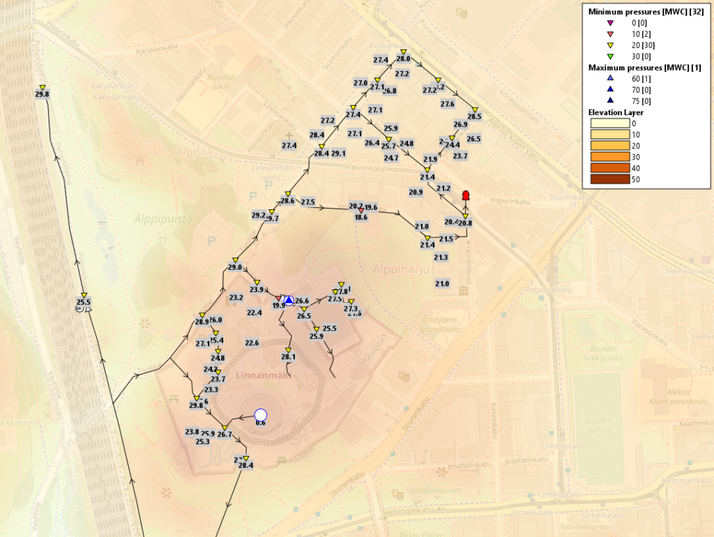
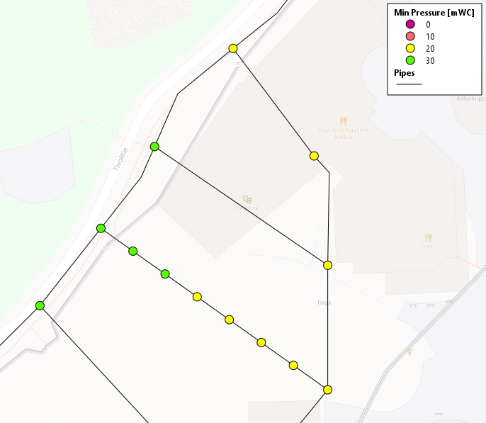
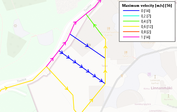
In hydraulic models, there is one component that you cannot find in real networks that is a node or junction component. It is an imaginary component that is in the end and beginning of every pipeline. Junctions are needed to solve the mathematical graph model of system flows. Graph models used in hydraulic models are deterministic, meaning that they yield the same results with the same input parameters. In the below pictures, there are a few results depicted: minimum pressures for junctions and maximum flows for pipes.
How to build hydraulic model?
Building a hydraulic model can be time-consuming and tedious work if it is done for the first time. The first and foremost information to add to the model is network information. Typically the information resides in a network information system or GIS system. There you can usually find the following things:
- Pipes (x, y, z, material, diameter)
- Valves (x, y, z, type)
- Pumps (x, y, z, pump curve)
- Tanks (x, y, z, volume)
- Water sources / Treatment plants (x, y, z)
A very important thing to understand about network data is, that all the pipes must have data model connections to each other. In other words, all the pipes must know the pipe before and pipe after. There cannot be pipes dangling without connection to nearby pipes. There are automatic methods to enhance the network data if you suspect it to be poor quality.
The next important system to dig information into the hydraulic model is the customer information system. This information can also be in the network information system or the GIS system. The following information is needed from customers to be input into the hydraulic model:
- Location (x, y, z)
- Consumption (m3 / year or even higher resolution consumption)
- Criticality of the customer (if collected)
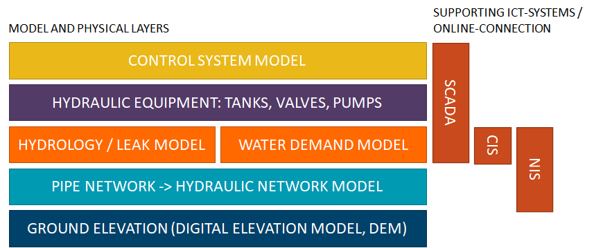
The driving force in hydraulic models, especially water and district energy models, are pumps, controls, tanks, and other operational units. They bring life into the model by moving the medium in the pipelines. The key software component in understanding how any specific network system works is the SCADA(Supervisory control and data acquisition). SCADA systems can be very complex depending on the system size. In a typical medium-sized (200 000 Inhabitat) network you would find dozens of pumping stations, a handful of water towers, and water sources. Digging into the SCADA system and its history database can be the most time-consuming phase of model building. From the SCADA system we need to find out the following data:
- Control parameters for all pumpings (control type and value)
- Flow and pressure data (base leakage and calibration purposes)
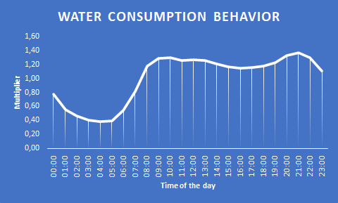
For the control parameters, we need to figure out whether the pumpings are pressure or flow-controlled or do we have some type of flow-compensated pressure control or vice-versa. The simplest control for a pumping station would be fixed pressure or fixed flow setting, but there will most certainly be more complex controls in place as well. If there are free-floating water towers in the system, the pumps have also shutdown limits due to water tower levels. Another important aspect that we can get out of the SCADA is flow and pressure history data. All the networks have a small amount of leakage and we can use the history data to calculate base leakage to areas when we know all the inputs, the water consumption, and all the outputs of the area. We can also use the history data to model the water consumption pattern for each area. Typical water consumption patterns look like the picture below:
Understanding deeply how the control system operates in a vast distribution system and translating the functionality into the hydraulic model, requires always very high-level expertise.
If you need assistance in building the model or understanding your distribution system controls, please contact us.
What is hydraulic modeling used for?
Hydraulic modeling is a very powerful tool for any utility or consultant working for utilities. The power of modeling is its flexibility, almost anything technical related to the network can be modeled. Modeling gives the user-ready answers to many “what if”-scenarios. Some of the typical cases where to use hydraulic modeling are:
- Pipe renovation and building – what is the right sized pipe?
- Can effect the renovation method and material size (no-dig -method or close pipe)
- Preplanning – to find the hydraulically best route
- Hydrant and spkrinler analyzes
- How much a utility can promise water to connection contract without risking their daily business
- New customer connections and increased demand on specific areas
- Customer connection contract (promised pressure and flow)
- Planning investments – Future analysis
- Where is the capacity the tightest in any given area
- Budget the overall costs
- Booster station and new water plant capacity planning
- Sizing booster stations
- Optimizing controls of the system
- The system has grown organically and the optimization of sub-stations can end up in poor overall optimization
- Modeling a contamination spread in the system
- To prepare for accident
- To simulate the extent of a real event
- Modeling the recovery of contamination
- Creating a specific chlorination program, what to do – where – how much
- Resolving any type of anomalities in the system
- Leakages, low pressures, quality issues
- To get overall understanding on how the system works
- It is very difficult to understand how the system behaves trough out the day, which way the water flows and how much on any particular pipe
Read more
- hydraulic modeling in water distribution systems
- modeling in district energy networks
- modeling in storm water and combined sewer systems
If you are wondering how you could utilize hydraulic modeling in your daily work, please contact us.